How do Solar Panel Wiring Design and Voltage Drop Issues Explained Clearly?
Solar panel wiring design matters because electricity must travel from the modules to the inverter and then to the service panel, with as little loss and as much safety as possible. Even when panels are producing strong power, poor wiring choices can reduce delivered energy, trigger nuisance inverter faults, or create long-term reliability problems. Voltage drop is one of the most common design concerns because long cable runs and undersized conductors can reduce the voltage arriving at the inverter below what the array is producing.
That drop turns into heat in the wires, wasting some energy and sometimes raising temperatures in conduits and junction boxes. Wiring design is also tied to code requirements, equipment ratings, and real-world conditions like rooftop heat and cold-weather voltage rise. A solid plan balances performance with protection, using proper conductor sizing, string configuration, and routing practices so the system operates steadily through daily and seasonal changes.
Keep losses low and safety high.
1. Understanding voltage drop in solar circuits
Voltage drop is the difference between the voltage at the source and the voltage at the destination after current travels through a conductor. In a solar system, it can happen on the DC side from modules to the inverter or combiner, and on the AC side from the inverter to the service panel. The drop grows with higher current, longer distance, and smaller wire gauge. Because power equals voltage times current, a drop in voltage at the same current means less power delivered to the inverter or to the grid connection point. The lost power is converted into heat in the conductors, which is why wiring that runs hot can be a sign of excessive resistance.
Designers aim to keep voltage drop modest so the system operates near its intended point, especially during high production hours when current is elevated. On the DC side, voltage drop can also affect the inverter’s ability to track the array’s operating point efficiently, particularly in low light when voltage margins are smaller. On the AC side, voltage drop can contribute to voltage rise at the service panel, reducing inverter output if grid voltage becomes too high. Good design starts by estimating the current for each circuit and calculating the acceptable drop for both performance and compliance.
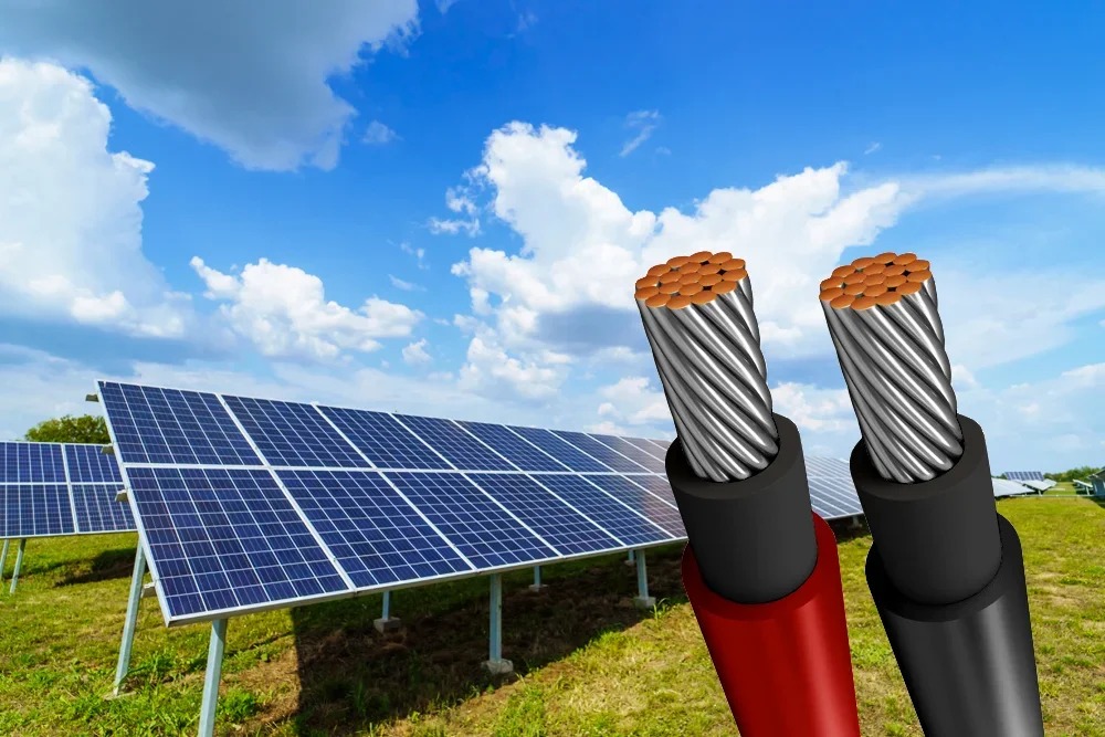
2. String configuration, wire sizing, and real distances
How you configure strings changes the current levels and, therefore, the voltage drop. Longer strings increase voltage and keep current the same, which can reduce voltage drop losses for a given wire size because losses depend heavily on current. However, longer strings must remain within the inverter’s voltage limits, especially in cold weather when module voltage rises. Parallel strings increase current, which can increase the risk of voltage drop unless the conductors are upsized. This is why combining multiple strings in a combiner box can require larger homerun conductors from the combiner to the inverter.
Physical layout matters too. The actual wire length is not just the straight-line distance; it includes vertical drops, routing around obstructions, conduit paths, and extra slack for service loops. Rooftop arrays with long runs to a garage inverter or a detached structure can add substantial distance, making conductor sizing more important than many homeowners expect. A contractor such as North Valley Solar Power may account for these routing realities early, because a design that looks fine on paper can exceed drop targets once real conduit paths are measured. Temperature also matters because conductor resistance rises as wires get hotter, so rooftop wiring in summer can experience slightly higher losses than the same circuit in cooler conditions.
3. DC side versus AC side issues and why both matter
DC and AC voltage drops affect the system differently. On the DC side, a larger drop means the inverter sees a lower voltage, which can reduce power transfer and can narrow the operating range, particularly at dawn, dusk, or during partial shading. It can also increase the likelihood that the inverter will fall below the minimum MPPT voltage under certain conditions, causing production to fluctuate.
Some inverters reduce output or disconnect to comply with grid rules when the voltage is outside limits. In that case, upsizing conductors can help lower resistive voltage drop along the run, allowing the inverter to stay online and produce power. This is a common issue in long AC runs to a distant interconnection point or in homes where the main panel is far from the inverter location.
Solar panel wiring design and voltage drop issues are closely linked because every foot of conductor and every amp of current influences how much energy reaches the inverter and the grid connection point. Voltage drop can reduce delivered power, create extra heat, and contribute to inverter operating problems on both the DC and AC sides.
Smart string configuration, accurate distance planning, proper conductor sizing, and careful attention to conduit fill and terminations help keep performance steady and reliability high. When the wiring plan is built around real routing conditions and temperature effects, the system is more likely to run smoothly, avoid nuisance faults, and deliver the energy production homeowners expect year-round.